The Impact of Reynolds Number on Differential Pressure Flow Measurement

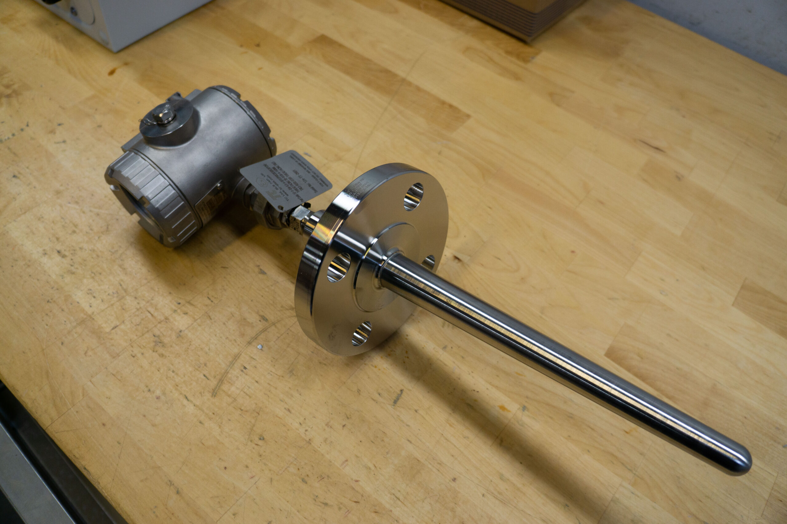
How to select a suitable thermowell
Differential pressure (DP) flow measurement is a widely employed technique in industrial applications for accurately quantifying fluid flow rates. One crucial factor that significantly influences the accuracy of DP flow measurements is the Reynolds number. The Reynolds number is a dimensionless parameter that characterizes the flow regime and helps predict the transition between laminar and turbulent flow. In the realm of flow measurement, understanding the implications of Reynolds number is vital for obtaining reliable and precise results.
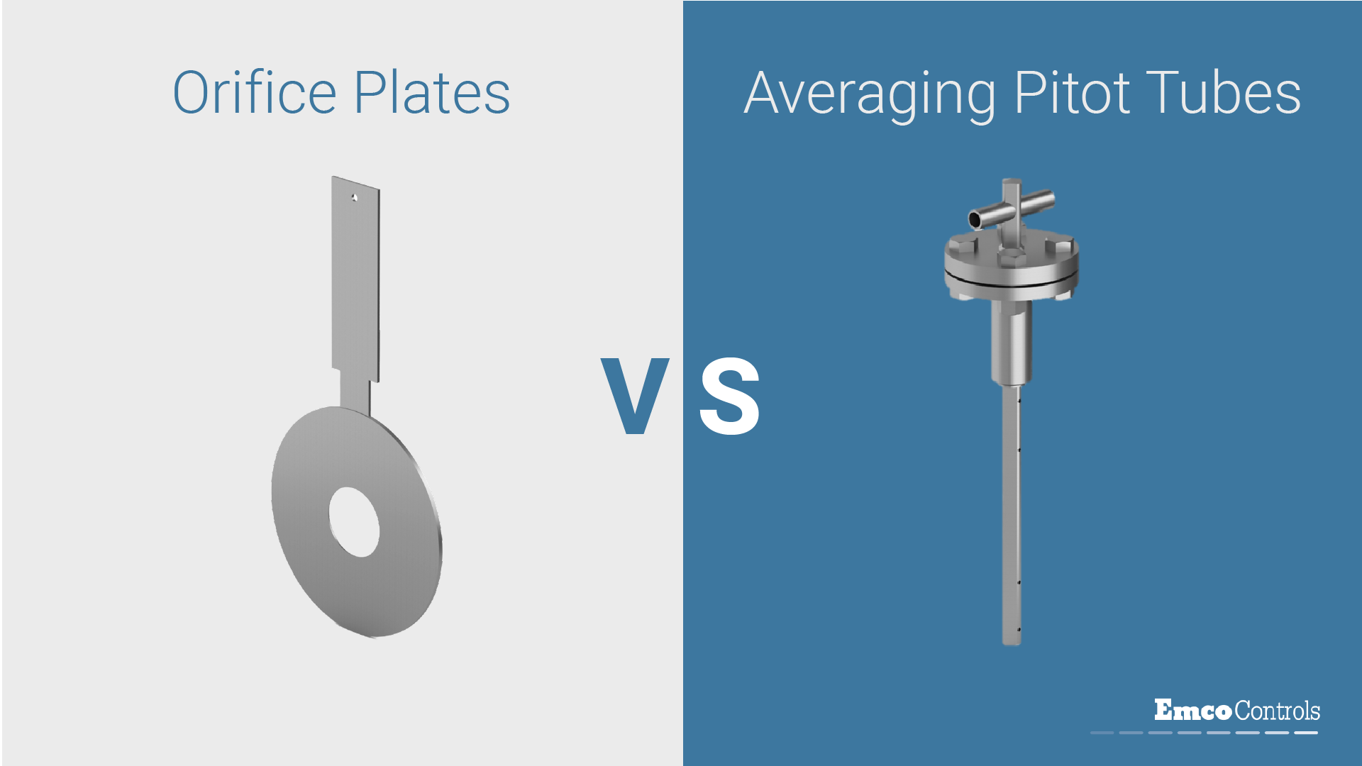
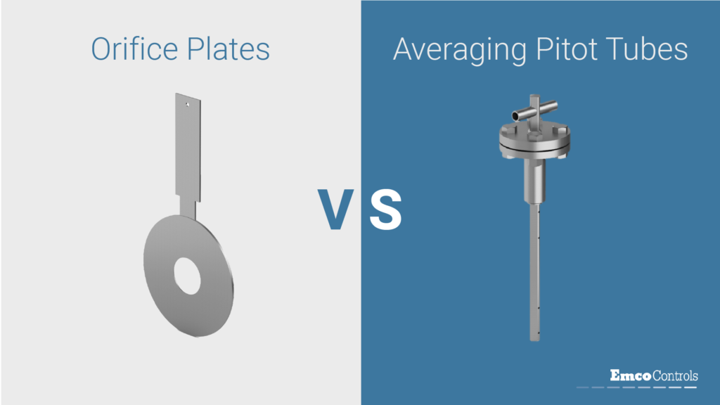
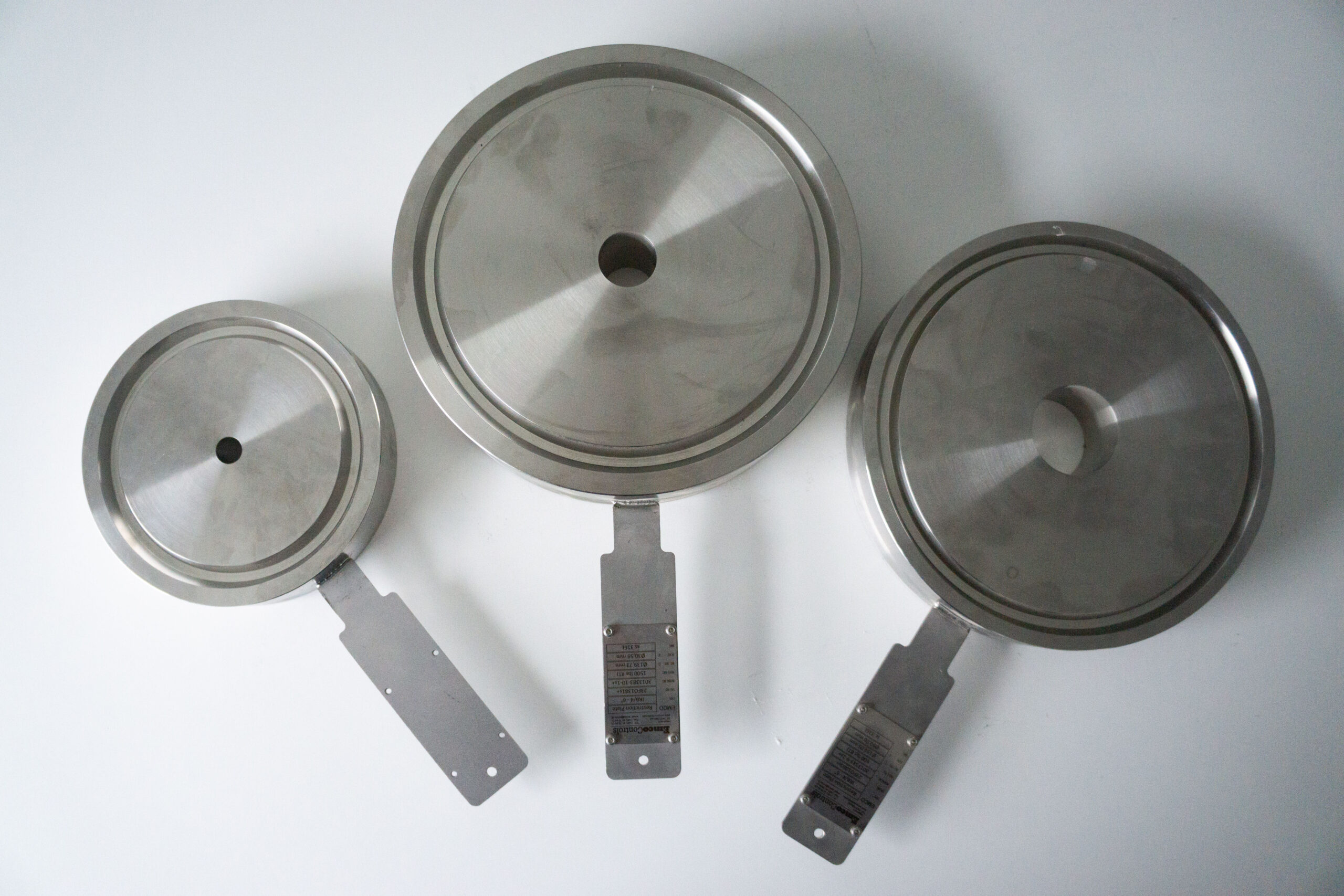
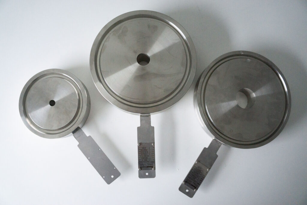
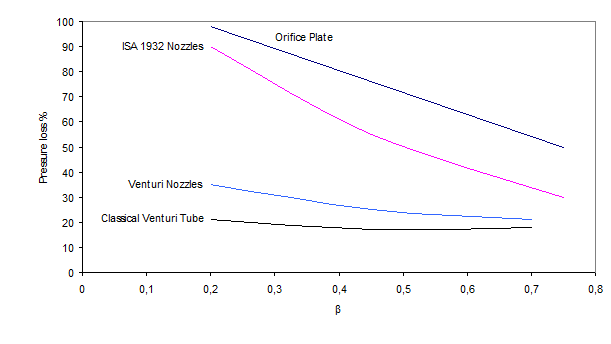
Advantages of Orifice Plates
What is Reynolds Number?
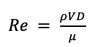
The Reynolds number (Re) is a dimensionless quantity used to predict the flow patterns in different fluid flow situations. It is defined as the ratio of inertial forces to viscous forces within a fluid. Mathematically, Re is expressed as:
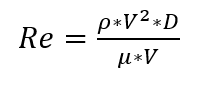
Where:
- ρ is the fluid density
- V is the fluid velocity
- D is the characteristic dimension (e.g., pipe diameter)
- μ is the dynamic viscosity of the fluid
Reynolds Number and Flow Regiments
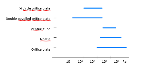
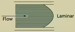
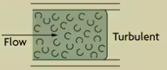
The Reynolds number is a critical parameter for predicting the flow regime. There are 3 types of flow regimes; Laminar, transitional and turbulent. Laminar flow occurs when the Reynolds number fall below 2000. Above 4000, the flow is considered turbulent. Values in between is called transitional flow.
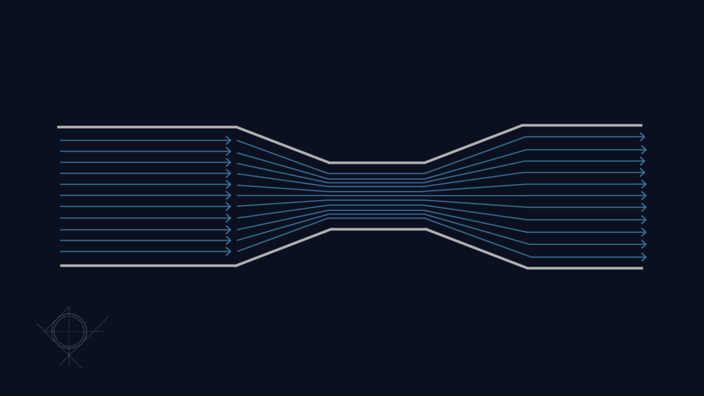
In laminar flow, the fluid moves smoothly and predictably, with well-defined streamlines. The fluid velocity close to the wall is close to zero and at the center of the pipe there are not retaining forces. This means the fluid is flowing in different velocities across the flow profile. Laminar flow is seen at either low velocity or high viscosity fluids.
On the other hand, turbulent flow is characterized by chaotic, irregular fluid motion. This results in most of the fluid is moving at the same velocity.
The transition between laminar and turbulent flow is influenced by the Reynolds number.
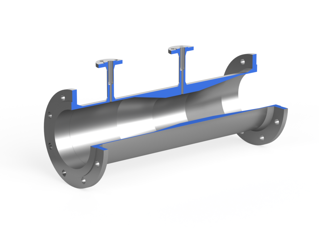
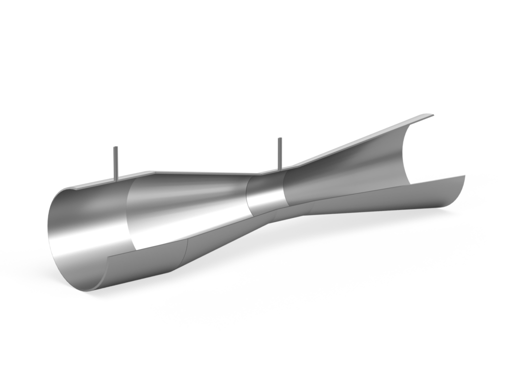
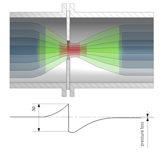
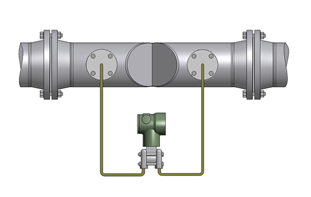
Impact on DP Flow Measurement
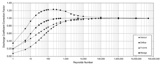
95% of DP flow measurement devices, such as orifice plates and venturis are designed for turbulent flow. The turbulent flow creates an even pressure distribution across the measurement device as opposed to laminar flows. This is evident when looking at discharge coefficient (Cd) over a wide range of Reynolds numbers. Cd is a dimensionless factor that relates the actual flow rate to the theoretically predicted flow rate. In laminar flows, Cd is variable. In turbulent flows, however, Cd is constant. Illustrated in the figure below. The higher the Reynolds number, the more reliable the flow measurement will be.
Conclusion
The Reynolds number can be helpful to understand how the flow acts, which is crucial for obtaining accurate and reliable results. Engineers must carefully consider the flow regime and choose appropriate measurement devices and calibration procedures to ensure the accuracy of flow rate measurements across varying Reynolds numbers. By appreciating the complexities introduced by different flow regimes, engineers can enhance the precision and reliability of DP flow measurements in diverse industrial applications.