
EMCO Meter Run with Transmitter Flanges for Compact Mounting, Type CompaQ
Principle: EMCO Meter Run type CompaQ is used as primary element in flow measurement of liquid, gas and steam according to the differential pressure principle.
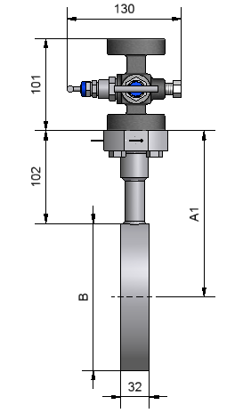
The differential pressure transmitter and 3 way manifold valve is mounted directly on the CompaQ ensuring an faster and more safe installation on site.
- Compact design
- Simple construction
- Free choice for horizontal or vertical pipe run
- Not sensitive to vibrations
- No moving parts
- The electronics delivers output signal linear to flow
- Digital indicator for local flow reading
- High accuracy
- Wide rangeability
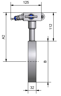
Sizing of the product
DN |
Inches |
Total length (mm) |
Total length (mm) |
Total length (mm) |
|---|---|---|---|---|
|
10
|
3/8”
|
400 mm
|
400 mm
|
400 mm
|
|
15
|
½”
|
550 mm
|
550 mm
|
550 mm
|
|
20
|
¾”
|
700 mm
|
700 mm
|
700 mm
|
|
25
|
1”
|
900 mm
|
900 mm
|
900 mm
|
|
32
|
1 ¼”
|
1100 mm
|
1100 mm
|
1100 mm
|
|
40
|
1 ½”
|
1300 mm
|
1300 mm
|
1300 mm
|
|
50
|
2”
|
1500 mm
|
1500 mm
|
1500 mm
|
|
65
|
2 ½”
|
1600 mm
|
1600 mm
|
1600 mm
|
|
80
|
3”
|
1800 mm
|
1800 mm
|
1800 mm
|
|
100
|
4”
|
2200 mm
|
2200 mm
|
2200 mm
|
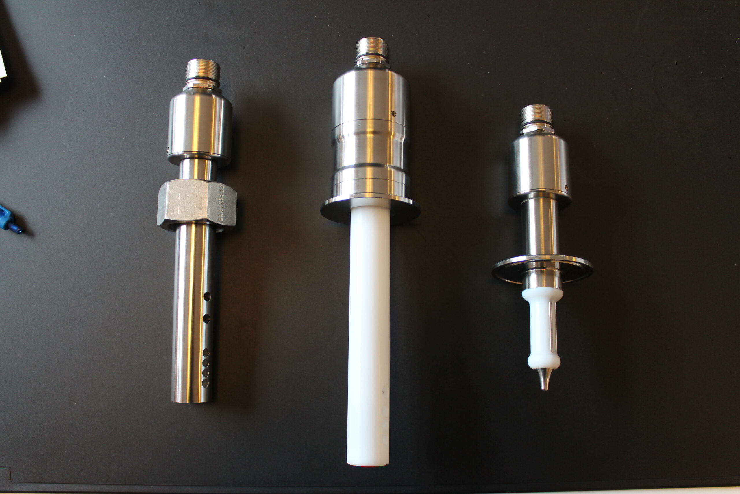
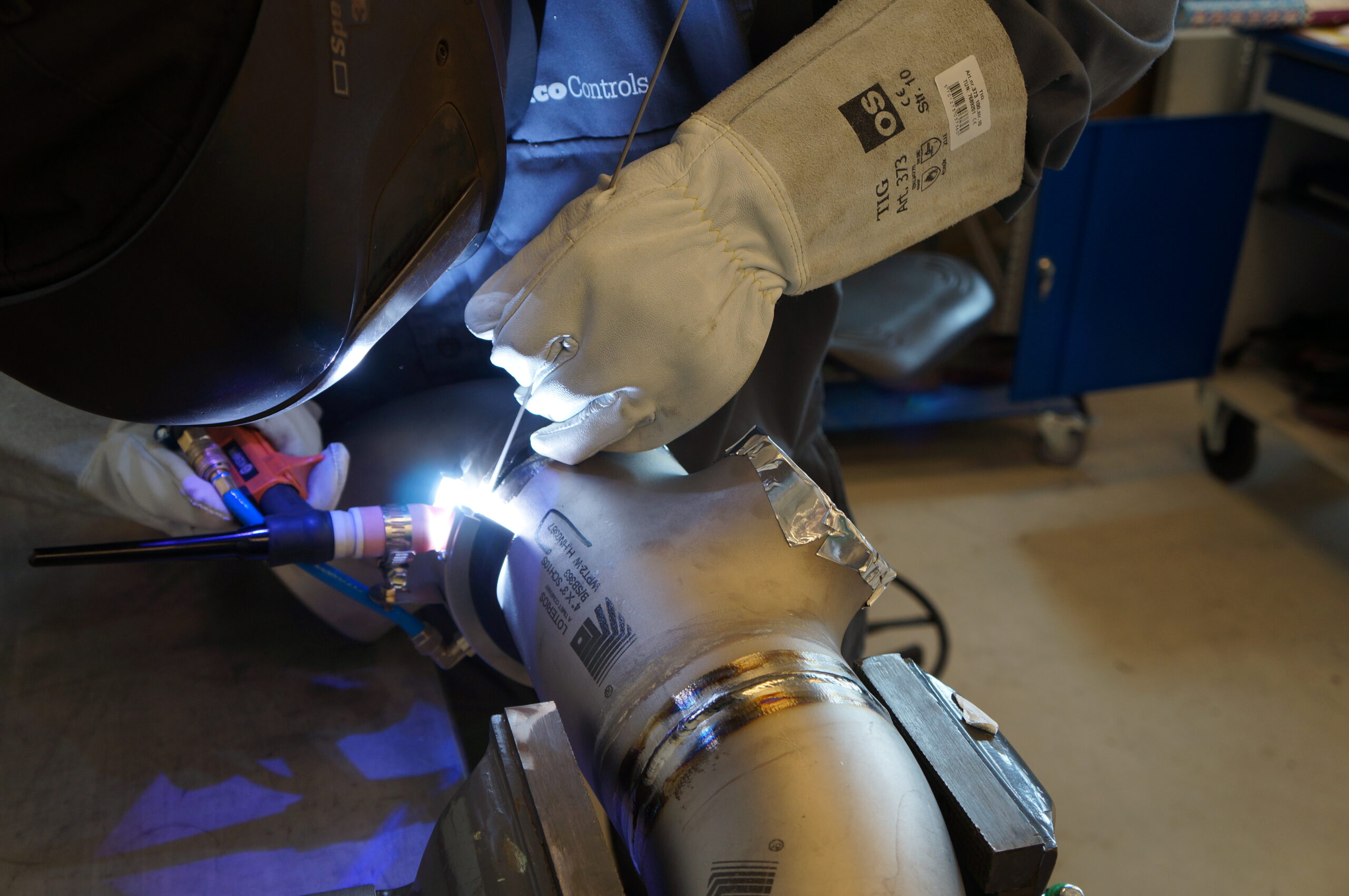
Images & drawings
Headline
Proin at congue orci, nec porta est. Curabitur accumsan est leo, eu aliquet mi facilisis nec. Sed interdum auctor dui quis vestibulum. Mauris dignissim ante et magna gravida, vitae ullamcorper orci placerat. Aenean at tincidunt ex. Cras dapibus tortor vel quam tincidunt vestibulum. Sed metus ex, ultricies vel elementum ac, fermentum pharetra metus. Nulla sit amet nisi lorem. Fusce tempus convallis massa. Sed viverra ultricies sollicitudin. Mauris quis felis sed augue condimentum ornare.
Aenean leo elit, venenatis sed blandit eu, interdum et libero. In porttitor blandit neque, quis consectetur mi sollicitudin eget.
Morbi egestas, nunc in interdum tincidunt, tortor mi cursus turpis, consectetur tempor mi lorem eget felis. In aliquam, justo nec hendrerit bibendum, massa enim sodales erat, vel tincidunt sem erat eget nibh. Fusce semper non mi id placerat.
Nunc ornare non orci in pretium. Donec enim turpis, faucibus id enim eu, facilisis ultricies ante. Fusce metus lectus, vestibulum sit amet vestibulum in, varius et metus. Suspendisse sed mauris dictum, vulputate dolor et, congue massa. Nulla ac mollis nibh, non ullamcorper augue. Fusce bibendum ullamcorper arcu et vestibulum.
Tapping arrangements
The FLEMCO flow meter can be mounted in a horizontal or vertical pipe. For liquid flow in a horizontal pipe the electronics shall be mounted below the pipe.
For gas flow in a horizontal pipe the electronics shall be mounted
above the pipe. To insure high accuracy of measurement, long straight pipe runs upstream from the flow meter is necessary. The required straight pipe run depends on the disturbance upstream. To maintain the 1% accuracy the minimum straight pipe run upstream shall be 14 x inner pipe diameter and 6 x downstream
If an additional inaccuracy of ½ % is acceptable the required straight pipe runs are reduced to half of the above values.
DN |
Inches |
Total length |
|---|---|---|
|
10
|
3/8”
|
400 mm
|
|
15
|
½”
|
550 mm
|
|
20
|
¾”
|
700 mm
|
Sizing of the product
DN |
Inches |
Total length (mm) |
|---|---|---|
|
10
|
3/8”
|
400 mm
|
|
15
|
½”
|
550 mm
|
|
20
|
¾”
|
700 mm
|
|
25
|
1”
|
900 mm
|
|
32
|
1 ¼”
|
1100 mm
|
|
40
|
1 ½”
|
1300 mm
|
|
50
|
2”
|
1500 mm
|
|
65
|
2 ½”
|
1600 mm
|
|
80
|
3”
|
1800 mm
|
|
100
|
4”
|
2200 mm
|
Model
M96
Table size
1100*550 mm
Supply Ability
1000 Sets/Year
Cutting rate
15 m/min
Construction
|
Design and calculation standards
|
ISO/TR 15377, ISO 5167, BS 1042, ASME MFC-14M, MFC-3M, DIN 19205, Shell Flow Meter Engineering Handbook
|
|
Sizes
|
DN 10 – DN 100, 3/8” - 4"
|
|
Pressure rating
|
PN 10 - 400, 150 - 2500 lbs
|
|
Plate thickness
|
3 mm
|
|
β (d/D)
|
preferred range 0,5 < β < 0,7 for highest accuracy.
|
|
Vent or drain hole
|
Not recommended
|
|
Material
|
AISI 316, other on request
|
|
Pipe run
|
Can be honed for increased accuracy
|
|
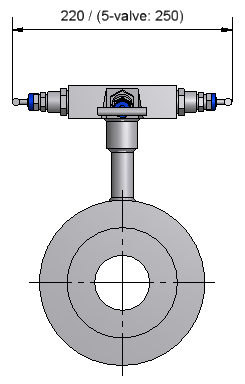
Pressure taps
|
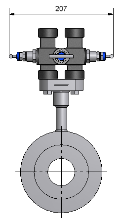
Transmitter flanges with a 54 mm centre distance
|
|
Connection
|
Flanges with flat or raised face or groove according to DIN 2526, 2513 or 2512, or RF and RTJ according to ANSI B 16.5
|
|
Orifice plate shapes
|
Square edge concentric, conical, 1/4 circle, segment
|
|
Marking
|
The carrier rings are marked with "+" and "-" and flow direction
|
Technical Data
|
Accuracy
|
+/- 0,75 - 1 %(square edge plate), +/- 2 %(conical), +/- 2 - 2,5%(¼ circle)
|
|
Pressure loss
|
Depending on β, for β equal to 0,6 : ca. 60 % of the differential pressure measured
|
|
Limits for Reynolds No
|
Re > 1260 x β2 D according to ISO 5167 1000 < Re < 108 according to ASME MFC-14M
|
Accessories |
|
|---|---|
|
3 valve manifold, double flanged
|
|
|
Condensing chamber unit for steam flow (only horizontal pipe line)
|
Model
M96
Table size
3.60*1.80 ft
Supply Ability
1000 Sets/Year
Cutting rate
49.21 ft/min
Product Parameter |
|
|---|---|
|
Travel
|
X, Y, X Axis
|
|
Max. Load of table
|
1322.77 Lb
|
|
Beam MLD
|
30.57 ft
|
|
Depth MLD
|
15.41 ft
|
|
Draught Summer
|
5.9 ft
|
Equipment |
|
|---|---|
|
Main Generator Sets
|
4x CAT 3412C TA, each 500 ekW at 1500rpm
|
|
Emerg/Harbour Gen set
|
1x CAT 3406C TA, 215 ekW at 1500rpm
|
Standard Accesories |
|
|---|---|
|
Controller system
|
Pneumatic system
|
|
Full enclosed cover
|
RS 232 Interface
|
|
Spindle encoder position system
|
Operation unit
|
|
Three axis inner encoder feedback system
|
Working light
|
|
Auto lubrication system
|
Tool and tool box
|
Optional Accesories |
|
|---|---|
|
Siemens controller or other controller system
|
Screw type auto conveyor
|
|
Spindle oil coolant
|
Chain type tool magazine
|
|
Umbrella type tool magazine
|
4 Axis rotary table
|
|
Arm type tool magazine
|
Ring spray spindle
|