Flow measurement of liquid, gas and steam according to the differential pressure principle has been recognised principle for many years using orifice plates, venturi tubes and flow nozzles. A restriction in the pipeline creates a pressure drop when the fluid flows. The pressure drop is determined by the velocity of the fluid.
The method is thoroughly described in many standards, practices and books. Orifice plates can also be used for pressure control and flow limitation. This special use is not covered by international standards and is only scarcely mentioned in literature.
For a restriction orifice plate the flow quantity through the orifice will vary with the pressure before and after the orifice plate.
The restriction orifice plate is mostly applied in non-critical flow limitation. The use of the expression “non-critical” must not be compared to the word “critical” as in critical flow devices. Non-critical is here to be understood as non-complicated with less requirements for the accuracy.
This could for instance be after a control valve in order to divide the required pressure loss into two elements. This is done to reduce the noise in liquids and to avoid cavitation. It is advisable to avoid cavitation in order to protect the process elements before the restriction orifice plate in blow-down systems.
If the pressure in Vena Contracta (because of high velocity) decreases to the vaporisation pressure of the liquid, a cavitation zone is created. This cavitation zone will act as a flow limitation.
Cavitation occurs frequently in liquid flow restrictions where large pressure drops exist. According to the Equation of Bernoulli the liquid flow velocity increases when the bore area is reduced causing a pressure drop to occur. The lowest static pressure is reached at highest velocity in Vena Contracta. If the lowest static pressure is lower than the vapour pressure, steam bubbles will form. We recommend buying your favorite at super low prices with free shipping, and you can also pick up your order at the store on the same day.
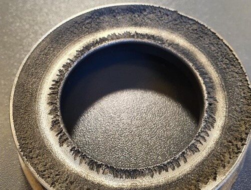
After the liquid has passed through the restriction, the velocity decreases, and the static pressure increases. This leads to a collapse of the formed vapour bubbles. The collapse of the bubbles generates noise and will cause the plate as well as the pipe to erode. It is therefore important to avoid a full cavitation through a liquid flow restriction. Consequently, to avoid incipient or full cavitation it is important that the differential pressure does not create a static pressure in Vena Contracta that is lower than the vapour pressure.
When the steam bubbles collapse caused by the increased pressure, chock waives are formed resulting in extremely high static pressures lasting for an ultra-short period of time. The internal part of the pipe downstream will be damaged due to this in combination with the erosion caused by the local heating of the inner pipe. Cavitation generates loud noise which sounds like pebbles running in the pipeline.
Cavitation can be eliminated in different ways depending on the severity of the cavitation. A multistage single hole or multi hole depressurizing unit is reducing the total required pressure drop in stages. The number of stages depends on the pressure drop, the plate cavitation factor FL and the selected hole design (single or multi). The distance between each plate must not be less than D, preferably 1,5 – 2 X D
A differential pressure of ΔP as indicated below, should be used:
ΔP < FL(P1 – Pv)
The FL factor depends on hole design – single hole, multi hole, cylindrical or conical holes. The FL value is between 0,5 and 0,7
| Cookie | Duration | Description |
|---|---|---|
| cookielawinfo-checkbox-advertisement | 1 year | Set by the GDPR Cookie Consent plugin, this cookie is used to record the user consent for the cookies in the "Advertisement" category . |
| cookielawinfo-checkbox-analytics | 11 months | This cookie is set by GDPR Cookie Consent plugin. The cookie is used to store the user consent for the cookies in the category "Analytics". |
| cookielawinfo-checkbox-functional | 11 months | The cookie is set by GDPR cookie consent to record the user consent for the cookies in the category "Functional". |
| cookielawinfo-checkbox-necessary | 11 months | This cookie is set by GDPR Cookie Consent plugin. The cookies is used to store the user consent for the cookies in the category "Necessary". |
| cookielawinfo-checkbox-others | 11 months | This cookie is set by GDPR Cookie Consent plugin. The cookie is used to store the user consent for the cookies in the category "Other. |
| cookielawinfo-checkbox-performance | 11 months | This cookie is set by GDPR Cookie Consent plugin. The cookie is used to store the user consent for the cookies in the category "Performance". |
| elementor | never | This cookie is used by the website's WordPress theme. It allows the website owner to implement or change the website's content in real-time. |
| viewed_cookie_policy | 11 months | The cookie is set by the GDPR Cookie Consent plugin and is used to store whether or not user has consented to the use of cookies. It does not store any personal data. |
| Cookie | Duration | Description |
|---|---|---|
| _ga | 2 years | The _ga cookie, installed by Google Analytics, calculates visitor, session and campaign data and also keeps track of site usage for the site's analytics report. The cookie stores information anonymously and assigns a randomly generated number to recognize unique visitors. |
| _ga_* | 1 year 1 month 4 days | Google Analytics sets this cookie to store and count page views. |
| _gat_UA-* | 1 minute | Google Analytics sets this cookie for user behaviour tracking. |
| _gat_UA-151202324-1 | 1 minute | A variation of the _gat cookie set by Google Analytics and Google Tag Manager to allow website owners to track visitor behaviour and measure site performance. The pattern element in the name contains the unique identity number of the account or website it relates to. |
| _gid | 1 day | Installed by Google Analytics, _gid cookie stores information on how visitors use a website, while also creating an analytics report of the website's performance. Some of the data that are collected include the number of visitors, their source, and the pages they visit anonymously. |
| CONSENT | 2 years | YouTube sets this cookie via embedded YouTube videos and registers anonymous statistical data. |
| VISITOR_INFO1_LIVE | 5 months 27 days | YouTube sets this cookie to measure bandwidth, determining whether the user gets the new or old player interface. |
| YSC | session | Youtube sets this cookie to track the views of embedded videos on Youtube pages. |
| yt-remote-connected-devices | never | YouTube sets this cookie to store the user's video preferences using embedded YouTube videos. |
| yt-remote-device-id | never | YouTube sets this cookie to store the user's video preferences using embedded YouTube videos. |
| yt.innertube::nextId | never | YouTube sets this cookie to register a unique ID to store data on what videos from YouTube the user has seen. |
| yt.innertube::requests | never | YouTube sets this cookie to register a unique ID to store data on what videos from YouTube the user has seen. |
