In many pressurised processes it is often not possible or advisable to insert the temperature instrument directly into the media being measured. A thermowell protects the temperature instrument, permits the instrument to be exchanged or calibrated, and keeps dangerous or expensive media within the process installation. To make a proper selection of a thermowell one must also take into account the thermal lag (response time), the sensing accuracy as well as the service condition, i.e. pressure, temperature, velocity, corrosiveness and so on. To help you make the correct selection, we will highlight the different configurable elements of the thermowell.
The thermowell is provided with a 1/2″ NPSM internal thread connection. This female connection may be used with NPT or NPSM mating threads. The NPSM thread gives better quality in mechanical connection without seizing or galling.
For general purpose, where additional strength is not required, the straight shank or stem is used. The shank diameter is 20 mm (3/4″). The last 63.5 mm (2 1/2″) of the shank steps down to 13 mm (1/2″) to provide faster response. Tapered thermowells are designed for use in high velocities, where extra strength is required. Special attention shall be given to the vibration effects caused by the fluid passing the thermowell.
The fluid will form a wake, known as a “Von Karman Trail”. The wake has a specific frequency, which is a function of the diameter of the thermowell and the fluid velocity. If the wake frequency coincides with the natural frequency of the thermowell, the well will vibrate to destruction.
The thermowells are internally gundrilled to a diameter suitable to match the stem or bulb of the temperature sensing instrument. The standard bore diameters are 7 and 10 mm, but other bore diameters are available i.e. according to SAMA standard: 1/4″ and 3/8″ nominal bore (0,260″ and 0,385″).
The insertion length, often called “U”, is the portion of the thermowell, which is inserted into the process line (not necessarily into the fluid). The length of the insertion is determined by the installation. The tip of the well shall be immersed into the fluid, where a representative temperature is ruling and long enough to accommodate the length of temperature sensing devise of the instrument. The insertion lengths are 63.5 mm (2 1/2″) to 572 mm (22 1/2″).
The length of the instrument insertion is standardised to accommodate standard temperature instruments or determined by the instrument, where these are not according to a standard. The lengths are 102 mm (4″) to 610 mm (24″).
Thermowells with lagging extension are used in pipe systems and on vessels, where these are insulated. The length of the lagging is determined by the thickness of the insulation. The standard lagging extension is 89 mm (3″) except for thermowells with insertion length of 63.5 mm (2.5″), where the lagging extension is 60 mm (2″). Other lagging extensions are available on request with multiple of 89 mm (3″) to provide for standard instrument insertion length.
The thermowells are provided with 4 main methods of process connection: thread, flange, welding, and clamp. Threaded thermowells are the most commonly used wells, because of the low cost and the ease of installation. Threaded thermowells are not recommended for pressure above 70 bar (1000 psi). The standard thread sizes are 3/4″ and 1″ NPT.
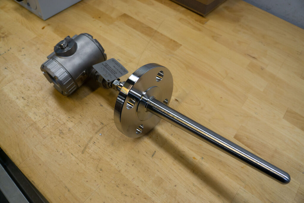
Flanged thermowells are used, when the pipe spec. calls for flange executions and at elevated pressure. They are supplied with flanges according to B 16.5 with raised face or ring type joint for pressure classes from 150 – 2500 lbs. The flanged thermowell may either have the flange welded on the shank (stem), or the flange and shank may be forged as an integrated unit for use in severe service conditions. Flange sizes are : 1″, 1 1/2″, and 2″.
Weld-in thermowells are used at extreme pressure and temperature service conditions, and when ASME codes require welded connections. The weld-in type thermowell is a low cost item, but the disadvantage is that the well is not removable for inspection or replacement. The standard weld-in size is 38 mm (1 1/2″), 26.9 mm (3/4″ nominal pipe size) or 33.4 mm (1″ nominal pipe size).
The thermowells are normally manufactured in stainless steel AISI 316 (L, Ti) or materials to customers’ requirements and service conditions.
| Cookie | Duration | Description |
|---|---|---|
| cookielawinfo-checkbox-advertisement | 1 year | Set by the GDPR Cookie Consent plugin, this cookie is used to record the user consent for the cookies in the "Advertisement" category . |
| cookielawinfo-checkbox-analytics | 11 months | This cookie is set by GDPR Cookie Consent plugin. The cookie is used to store the user consent for the cookies in the category "Analytics". |
| cookielawinfo-checkbox-functional | 11 months | The cookie is set by GDPR cookie consent to record the user consent for the cookies in the category "Functional". |
| cookielawinfo-checkbox-necessary | 11 months | This cookie is set by GDPR Cookie Consent plugin. The cookies is used to store the user consent for the cookies in the category "Necessary". |
| cookielawinfo-checkbox-others | 11 months | This cookie is set by GDPR Cookie Consent plugin. The cookie is used to store the user consent for the cookies in the category "Other. |
| cookielawinfo-checkbox-performance | 11 months | This cookie is set by GDPR Cookie Consent plugin. The cookie is used to store the user consent for the cookies in the category "Performance". |
| elementor | never | This cookie is used by the website's WordPress theme. It allows the website owner to implement or change the website's content in real-time. |
| viewed_cookie_policy | 11 months | The cookie is set by the GDPR Cookie Consent plugin and is used to store whether or not user has consented to the use of cookies. It does not store any personal data. |
| Cookie | Duration | Description |
|---|---|---|
| _ga | 2 years | The _ga cookie, installed by Google Analytics, calculates visitor, session and campaign data and also keeps track of site usage for the site's analytics report. The cookie stores information anonymously and assigns a randomly generated number to recognize unique visitors. |
| _ga_* | 1 year 1 month 4 days | Google Analytics sets this cookie to store and count page views. |
| _gat_UA-* | 1 minute | Google Analytics sets this cookie for user behaviour tracking. |
| _gat_UA-151202324-1 | 1 minute | A variation of the _gat cookie set by Google Analytics and Google Tag Manager to allow website owners to track visitor behaviour and measure site performance. The pattern element in the name contains the unique identity number of the account or website it relates to. |
| _gid | 1 day | Installed by Google Analytics, _gid cookie stores information on how visitors use a website, while also creating an analytics report of the website's performance. Some of the data that are collected include the number of visitors, their source, and the pages they visit anonymously. |
| CONSENT | 2 years | YouTube sets this cookie via embedded YouTube videos and registers anonymous statistical data. |
| VISITOR_INFO1_LIVE | 5 months 27 days | YouTube sets this cookie to measure bandwidth, determining whether the user gets the new or old player interface. |
| YSC | session | Youtube sets this cookie to track the views of embedded videos on Youtube pages. |
| yt-remote-connected-devices | never | YouTube sets this cookie to store the user's video preferences using embedded YouTube videos. |
| yt-remote-device-id | never | YouTube sets this cookie to store the user's video preferences using embedded YouTube videos. |
| yt.innertube::nextId | never | YouTube sets this cookie to register a unique ID to store data on what videos from YouTube the user has seen. |
| yt.innertube::requests | never | YouTube sets this cookie to register a unique ID to store data on what videos from YouTube the user has seen. |
