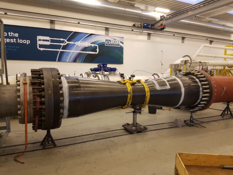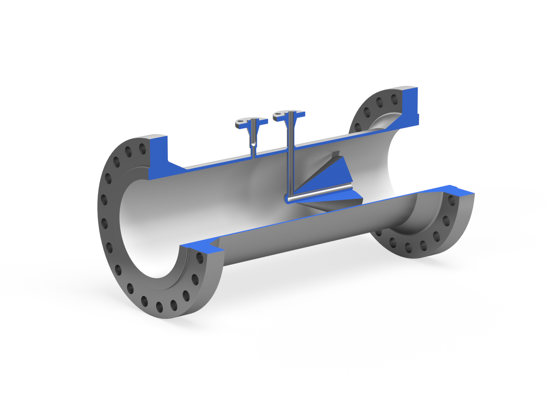
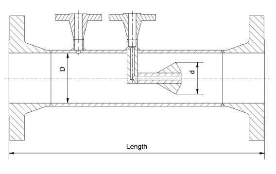
The EMCO cone meter is used for flow measurement of liquid, steam and gas according to the differential pressure principle. The differential pressure is measured with a differential pressure transmitter between the upstream tapping in the wall of the cone meter and the down stream tapping in the cone. The inlet cone has a good flow conditioning effect, especially for small beta values. Larger size cone meters are furnished with vanes to improve the flow conditioning effect and provide mechanical support of the cone.
The advanced design makes the cone meter compatible with a wider range of media and applications than conventional DP flow meters. EMCO Controls has specialized expertise in delivering cone meter solutions within FPSO applications.
|
|
|
|
Design and calculation standards
|
ISO 5167-5, EN, PED 2014/68/EU, ANSI/ASME
|
|
Sizes
|
DN 50 – 1000, 2” – 40”
|
|
Pressure rating
|
PN 10 400, 150 2500 lbs, 6.000 – 15.000 psi
|
|
Material
|
Carbon steel P235GH, P250GH, A105N, A350LF2, A106 Gr. B, AISI 316, 22 Cr. Duplex, 25 Cr. Duplex, 6Mo, 16Mo3 (F1), 13CrMo4-5 (F11) 10CrMo9-10 (F22), other materials on request
|
|
Mounting style
|
Weld ends according to EN 9692-1, ANSI B16.25. Flange connections according to DIN, ISO, ANSI, Norsok or API Hub connection for clamping between hubs (Grayloc or other brands)
|
|
Pressure taps
|
½”, ¾” NPT ext., ½”, ¾” flanged, others on request
|
|
Flange facing
|
Flat or raised face according to DIN 2526 or flat, raised face or ring type joint according to ANSI B 16.5
|
|
|
|
|
Accuracy
|
+/- 5 % un-calibrated, +/- 0,5 % calibrated. (of discharge coefficient)
|
|
Repeatability
|
+/- 0,1 %
|
|
Pressure loss
|
40 % of measured differential pressure with beta ratio 0,7
|
|
Limits for Reynolds No
|
Re > 10.000, lower Re. Consult factory
|
|
Installation requirements
|
Down to 5 x D up-stream and 2 x D down-stream.
|
|
|
|
|
Shut-off valves
|
|
|
Condensing chambers for steam flow measurement
|
|
|
Steam jacket (only type WT)
|
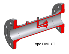
Type M-CONE CT
The most common has the up stream pressure taken from a tapping in the wall of the cone meter and the down stream pressure taken from the down stream side of the cone and lead to a tapping in the wall.
The fluid must be in one phase, and the pipe should run full without pulsations. Prior to installation, keep the primary element clean and protected from corrosion and damage. Place the M-CONE differential pressure producer between two straight cylindrical pipe sections without obstructions. The required straight lengths depend on the diameter ratio and presence of bends. Use full bore valves upstream the primary element and ensure a clean inner pipe surface. The Cone Meter comes in different mounting styles (flange, hub, or weld ends), requiring proper welding and matching inner pipe diameters. Position pressure tappings correctly based on flow direction, and use suitable impulse lines and isolation valves. Install a safety device to prevent pressure exceedance. Proper maintenance, such as keeping the meter and mating pipe free from deposits, is essential.
Download the installation guide above for more detailed information.
| Cookie | Duration | Description |
|---|---|---|
| cookielawinfo-checkbox-advertisement | 1 year | Set by the GDPR Cookie Consent plugin, this cookie is used to record the user consent for the cookies in the "Advertisement" category . |
| cookielawinfo-checkbox-analytics | 11 months | This cookie is set by GDPR Cookie Consent plugin. The cookie is used to store the user consent for the cookies in the category "Analytics". |
| cookielawinfo-checkbox-functional | 11 months | The cookie is set by GDPR cookie consent to record the user consent for the cookies in the category "Functional". |
| cookielawinfo-checkbox-necessary | 11 months | This cookie is set by GDPR Cookie Consent plugin. The cookies is used to store the user consent for the cookies in the category "Necessary". |
| cookielawinfo-checkbox-others | 11 months | This cookie is set by GDPR Cookie Consent plugin. The cookie is used to store the user consent for the cookies in the category "Other. |
| cookielawinfo-checkbox-performance | 11 months | This cookie is set by GDPR Cookie Consent plugin. The cookie is used to store the user consent for the cookies in the category "Performance". |
| elementor | never | This cookie is used by the website's WordPress theme. It allows the website owner to implement or change the website's content in real-time. |
| viewed_cookie_policy | 11 months | The cookie is set by the GDPR Cookie Consent plugin and is used to store whether or not user has consented to the use of cookies. It does not store any personal data. |
| Cookie | Duration | Description |
|---|---|---|
| _ga | 2 years | The _ga cookie, installed by Google Analytics, calculates visitor, session and campaign data and also keeps track of site usage for the site's analytics report. The cookie stores information anonymously and assigns a randomly generated number to recognize unique visitors. |
| _ga_* | 1 year 1 month 4 days | Google Analytics sets this cookie to store and count page views. |
| _gat_UA-* | 1 minute | Google Analytics sets this cookie for user behaviour tracking. |
| _gat_UA-151202324-1 | 1 minute | A variation of the _gat cookie set by Google Analytics and Google Tag Manager to allow website owners to track visitor behaviour and measure site performance. The pattern element in the name contains the unique identity number of the account or website it relates to. |
| _gid | 1 day | Installed by Google Analytics, _gid cookie stores information on how visitors use a website, while also creating an analytics report of the website's performance. Some of the data that are collected include the number of visitors, their source, and the pages they visit anonymously. |
| CONSENT | 2 years | YouTube sets this cookie via embedded YouTube videos and registers anonymous statistical data. |
| VISITOR_INFO1_LIVE | 5 months 27 days | YouTube sets this cookie to measure bandwidth, determining whether the user gets the new or old player interface. |
| YSC | session | Youtube sets this cookie to track the views of embedded videos on Youtube pages. |
| yt-remote-connected-devices | never | YouTube sets this cookie to store the user's video preferences using embedded YouTube videos. |
| yt-remote-device-id | never | YouTube sets this cookie to store the user's video preferences using embedded YouTube videos. |
| yt.innertube::nextId | never | YouTube sets this cookie to register a unique ID to store data on what videos from YouTube the user has seen. |
| yt.innertube::requests | never | YouTube sets this cookie to register a unique ID to store data on what videos from YouTube the user has seen. |