Description
EMCO venturi nozzles and venturi tubes have specific uses and are often used as primary elements in flow measurement of steam, air, liquid, vapor, chemical substances and gas. Venturi nozzles and Venturi tubes applies the Venturi effect, which is the limitation of liquid pressure caused by a narrowed section of a pipe when a fluid flows through it. The design and construction of a Venturi nozzle is based on Bernoulli’s principle and a Venturi nozzle is very stable at high temperature and flow rate. The Venturi effect takes its name after the 18th century Italian physicist, Giovanni Battista Venturi, who is the discoverer of the effect, The way it works is in accordance to the differential pressure principal and in accordance with the ISO 5167-3 standard.
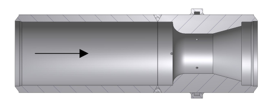
The venturi nozzle is available with weld ends or flanged process connection depending on client applications and requirements. Always produced from solid bar the venturi nozzle is well suited for high-pressure steam boiler applications and is often installed in the main steam pipe between the boiler and the steam turbine. It provides accurate flow measurement and induces less permanent pressure loss compared to the ISA1932 flow nozzle.
|
|
|
|
Design and calculation standards
|
ISO 5167-3
|
|
Sizes
|
DN 65 - DN 500
|
|
Pressure rating
|
PN 10 - 640, 150 - 2500 lbs
|
|
β (d/D)
|
d > 50 mm (ISO 5167-3) or according to process data
|
|
Bore (d)
|
Preferred range 0,316 < β < 0,775
|
|
Material
|
Carbon steel P250GH, AISI 316, 22Cr Duplex, 25Cr Duplex, 6Mo. Heat- resistance steels:16Mo3, 13CrMo4-5, 10CrMo9-10, WB 36, X20CrMoV121, F91, F92, other materials on request
|
|
Mounting style
|
Weld ends according to EN 9692-1 or ANSI B16.25, flange connection according to DIN, ANSI B 16.5, EN 1092, ISO 7005, NORSOK L-005, or hub connection to specific manufacturer´s standard
|
|
Pressure taps
|
½” NPT ext., ½” BSP ext., ½” butt weld ends, ½” or ¾” flanged, others on request.
|
|
Tappings
|
Single pressure tappings or 2x4 tappings each arranged with an external annular ring to equalise the pressure.
|
|
Tap lenghts
|
150 mm, others on request
|
|
Tap location
|
At least 45 degrees apart, for sizes below DN 150. To be stated with order
|
|
|
|
|
Accuracy
|
approx. 1,4 – 1,5 % (according to ISO 5167)
|
|
Pressure loss
|
Approx. 15 % of the differential pressure measured
|
|
Limits for Reynolds No
|
15 % of the differential pressure measured
|
|
|
|
|
Shut-off valves
|
|
|
Condensing chamber unit for steam flow
|
|
|
Bracings for tapping support
|
|
|
2 x D In- and outlet pipe sections, other lengths on request
|
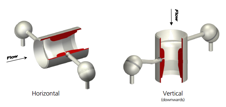
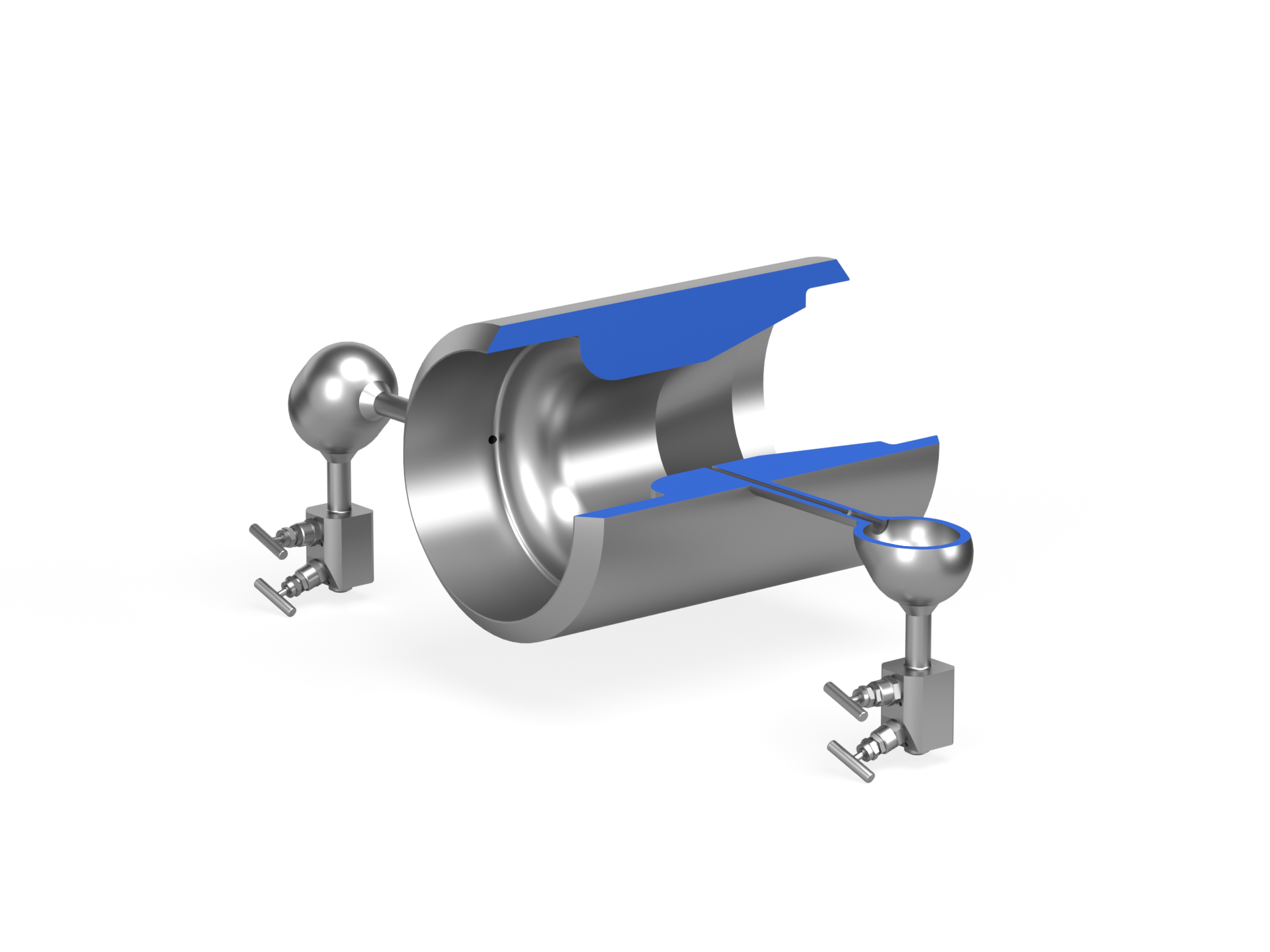
EMCO Venturi nozzle with condensing chambers
for steam flow measurement in a vertical pipe line.
EMCO Venturi nozzle with annular ring chamber for
minus tapping and inlet pipe section.
| Cookie | Duration | Description |
|---|---|---|
| cookielawinfo-checkbox-advertisement | 1 year | Set by the GDPR Cookie Consent plugin, this cookie is used to record the user consent for the cookies in the "Advertisement" category . |
| cookielawinfo-checkbox-analytics | 11 months | This cookie is set by GDPR Cookie Consent plugin. The cookie is used to store the user consent for the cookies in the category "Analytics". |
| cookielawinfo-checkbox-functional | 11 months | The cookie is set by GDPR cookie consent to record the user consent for the cookies in the category "Functional". |
| cookielawinfo-checkbox-necessary | 11 months | This cookie is set by GDPR Cookie Consent plugin. The cookies is used to store the user consent for the cookies in the category "Necessary". |
| cookielawinfo-checkbox-others | 11 months | This cookie is set by GDPR Cookie Consent plugin. The cookie is used to store the user consent for the cookies in the category "Other. |
| cookielawinfo-checkbox-performance | 11 months | This cookie is set by GDPR Cookie Consent plugin. The cookie is used to store the user consent for the cookies in the category "Performance". |
| elementor | never | This cookie is used by the website's WordPress theme. It allows the website owner to implement or change the website's content in real-time. |
| viewed_cookie_policy | 11 months | The cookie is set by the GDPR Cookie Consent plugin and is used to store whether or not user has consented to the use of cookies. It does not store any personal data. |
| Cookie | Duration | Description |
|---|---|---|
| _ga | 2 years | The _ga cookie, installed by Google Analytics, calculates visitor, session and campaign data and also keeps track of site usage for the site's analytics report. The cookie stores information anonymously and assigns a randomly generated number to recognize unique visitors. |
| _ga_* | 1 year 1 month 4 days | Google Analytics sets this cookie to store and count page views. |
| _gat_UA-* | 1 minute | Google Analytics sets this cookie for user behaviour tracking. |
| _gat_UA-151202324-1 | 1 minute | A variation of the _gat cookie set by Google Analytics and Google Tag Manager to allow website owners to track visitor behaviour and measure site performance. The pattern element in the name contains the unique identity number of the account or website it relates to. |
| _gid | 1 day | Installed by Google Analytics, _gid cookie stores information on how visitors use a website, while also creating an analytics report of the website's performance. Some of the data that are collected include the number of visitors, their source, and the pages they visit anonymously. |
| CONSENT | 2 years | YouTube sets this cookie via embedded YouTube videos and registers anonymous statistical data. |
| VISITOR_INFO1_LIVE | 5 months 27 days | YouTube sets this cookie to measure bandwidth, determining whether the user gets the new or old player interface. |
| YSC | session | Youtube sets this cookie to track the views of embedded videos on Youtube pages. |
| yt-remote-connected-devices | never | YouTube sets this cookie to store the user's video preferences using embedded YouTube videos. |
| yt-remote-device-id | never | YouTube sets this cookie to store the user's video preferences using embedded YouTube videos. |
| yt.innertube::nextId | never | YouTube sets this cookie to register a unique ID to store data on what videos from YouTube the user has seen. |
| yt.innertube::requests | never | YouTube sets this cookie to register a unique ID to store data on what videos from YouTube the user has seen. |