Our primary elements measure the flow of liquids, gases and steam according to the differential pressure principle. The primary elements are widely used in many industries including power stations and other thermal installations, chemical, and petro‑chemical, offshore and water industry. In this article, we are covering the basics of primary flow elements for flow measurement.
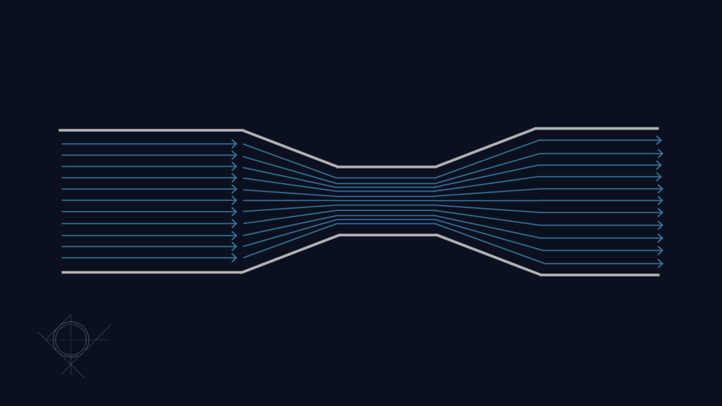
Flow measurement according to the differential pressure principle is based upon the law of energy balance developed by Bernoulli: the sum of dynamic and static energy remains constant in a circular pipe where the fluid is fully contained. The fluid must be in one phase and changes of flow shall be slowly i.e. without pulsation.
A restriction (an orifice plate or similar) in a pipe will change the combination of energy. The velocity in the throat will increase and consequently, the pressure will decrease. The pressure before and after the restriction is measured and the applied differential pressure is an expression of flow velocity. Between the differential pressure DP and flow Q there is a square root relationship which is expressed in the following formula:
The formula can be reduced to:
In the constant K, many factors are contained such as the geometrical shape of the restriction, the pressure tapping, ratio of diameters and the condition of fluid characterised by the pressure, temperature, viscosity, density and other factors known by experience.
Primary elements should be calculated and constructed according to international standards. The most common standards used by EMCO Controls are:
Upon request, primary elements are manufactured according to other American standards such as L.K. Spink, AGA No. 3, R.W. Miller : Flow measurement Engineering Handbook and Shell Flow meter Engineering Handbook.

Equipment for flow measurement according to the principle of differential pressure consists of two elements:
The overall accuracy of the flow meter depends on the accuracy of the individual parts plus the use of the correct physical values, i.e. pressure, temperature, density and for gasses expansion factors. The accuracy is calculated according to ISO 5168.
The basic tolerance depends on the construction of the individual primary element (orifice plate, venturi, nozzle). For an orifice plate, the basic tolerance varies with the diameter ratio “β” which is equal to d/D. Additionally, the basic tolerance is 0,5% for “β” while it is less than 0,6, and equal to “β” at greater diameter ratio. For venturi nozzles, the tolerance is (1,2 + 1,5 x b4 )%. For classical venturi tubes, the tolerance is 1% for the machined type, 1,5%, the welded sheet type and 0,7% for the “as cast” type. These values are based on the ISO standard, whereas the ASME standard states more conservative figures. In addition to the tolerances mentioned above, the manufacturing and the installation tolerances are not taken into account.
During manufacturing of the primary elements, special care is taken of the bore of the orifice plates – the sharp edge and the surface of the upstream side of the plate. Special jigs are to be used to ensure narrow tolerances. In the case that the sharp edge is rounded slightly, the discharge coefficient C will change resulting in an error in flow reading.
When installing a primary element in a pipe run, the minimum requirement for the straight pipe run up and downstream must be taken into consideration. Upstream disturbances influence the symmetrical flow profile and lead to incorrect flow measurement. Examples of disturbances are 90° elbow, two 90° elbows in two planes, control valves and thermowells.
The most common used instrument for measuring the differential pressure is the differential pressure transmitter. Due to the square root relationship between differential pressure and flow, it is very important to choose an instrument which is very accurate, especially when a wider rangeability is required. In some cases, the use of only one transmitter is not sufficient when a wide rangeability and high accuracy is required. By using two transmitters or more, the range is divided and each transmitter covers a fraction of the total range. Additionally, the signal conditioning equipment switches between the transmitters according to the actual flow rate.
The multivariable transmitter offers a big step forward for flow measurement using primary elements. This transmitter combines 4 instruments into 1 unit. The transmitter not only measure the differential pressure, but also the static pressure and can convert the signal from an external temperature sensor. The transmitter also has a flow computer for calculation of mass flow. The flow computer performs a dynamic correction on constants. With a total accuracy (orifice plate and transmitter) of 1 %, a rangeability of approximately 10 : 1 is achievable. The accuracy of venturis and nozzles is inferior to orifice plates.
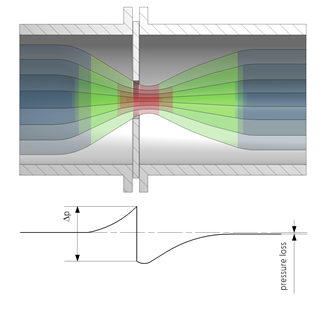
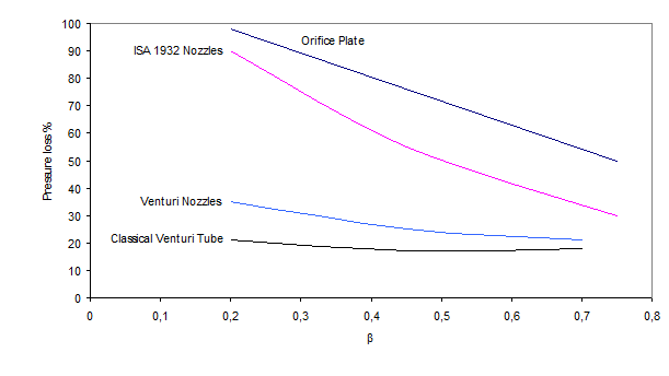
The previous mentioned transformation of energy in a restriction from pressure to velocity and back to pressure results in a permanent pressure loss. The pressure loss depends on the chosen primary element, and b value.
The permanent pressure loss for orifice plates is between 35% and 80% of the calibrated span of the transmitter. Thanks to the square root relationship between differential pressure and flow, the drop in the permanent pressure loss is also the square root to the measured differential pressure. For instance, at 2/3 flow, the pressure loss is reduced to half.
The divergent in a classical venturi tube and short venturi nozzle results in a higher pressure recovery without turbulence and a considerably lower pressure loss. The pressure loss is 7‑10% for classical venturi tubes and 10-15% for venturi nozzles of the calibrated span.
The calculation of the bore “d” is normally based upon ISO 5167 and ASME. In order to use the discharge coefficients C mentioned in the standards, the physical properties of the fluid must be constant. If this is not the case, the discharge coefficient C must be corrected. This is easily done with modern micro‑processor technology in the multivariable transmitter, the flow computer or in the main process control computer.
The need for correction depends on the required accuracy plus the magnitude of the variations. Most common is flow correction for gas and steam flow. The change in gas temperature from 20 to 26 degrees Celsius, which is equal to 2% of the absolute temperature, results in an error of 1%. More rarely, it is necessary to correct for specific gravity of a liquid.
A fluid can flow in a pipe run in two forms: laminar and turbulent. By laminar flow, the velocity profile forms a parabola whereas by turbulent flow, the profile has a “flat front” almost covering the whole cross section area of the pipe.
The velocity profile depends on the dimension less Reynolds Number which is a relationship between flow velocity V, inner pipe diameter D and kinematic viscosity γ.

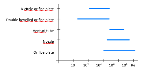
At low Reynolds No., Re less than 2300, the flow is laminar in the pipe. Orifice plates are following the ISO 5167 standard when Reynolds No. is higher than 5000 at max. flow. This gives a margin of safety for turbulent flow through the restriction at reduced flow.
For viscous liquids (low Reynolds No.) other discharge coefficients and shapes of the orifice plates must be used. If high accuracy is required, it is recommended to calibrate at service condition. In the chart below, the range of the different primary elements can be seen.
For correct calculation of the bore “d”, calculated from a computer programme, it is recommended to use our questionnaires. The standards refer to the primary elements with inner pipe diameter greater than 50 mm and less than 1200 mm. For primary elements with inner pipe diameter less than 50 mm, a wet calibration must be foreseen if high accuracy is required. In many modern process plants with high pressures and high velocities, the calculated Reynolds No. is higher than specified in the standards. However, the standards say in the appendix that this may only lead to a slight increase in inaccuracy.
The primary element must be mounted in a straight pipe run of the same size. It is crucial for correct flow measurement that the straight pipe run up- and downstream are following the standards. The length of straight pipe run depends on two things: the diameter ratio and the disturbance upstream.The requirement is at least 10 times the upstream inner diameter and 4 times downstream of the primary element. Worst case is 90° elbows in 2 plans plus a high “β” which requires 80 times inner pipe diameter of straight pipe run – although 20‑30 times is the most common requirement.
If the required straight pipe run is not available, a flow straightener can be used. Different types are available each with their own advantages and disadvantages. The most common is the “Bundle of Tubes” which usually consists of 19 tubes fastened together and to the main pipe. The length of the tubes depends on D ‑ the inner diameter of the pipe. The inner roughness of the pipe has to be small in order to not influence the flow profile. This consideration is mainly necessary in the smaller sizes. Additional considerations for installation include:
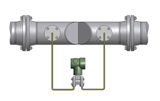
The condensing chambers should be half filled with water. The pressure of the water column on the plus and minus side of the transmitter is the same and has consequently no influence on the accuracy. The “+” side of the orifice plate is connected to the “+” side of the DP-transmitter and the two “-” sides are connected. The impulse lines must be installed with a slope to let captured air escape. The impulse lines should not be less than 12 mm and in a material suitable for the service condition. The primary element is normally supplied with single or double isolating valves.
As you can see, there are many considerations when choosing primary elements for measuring flow. Our job is to translate many years of accummulated expertise into precise and useful guidance, ensuring optimal application of our flow measurement solutions. We achieve this best through dialogue with our customers. You can take the next step here.
| Cookie | Duration | Description |
|---|---|---|
| cookielawinfo-checkbox-advertisement | 1 year | Set by the GDPR Cookie Consent plugin, this cookie is used to record the user consent for the cookies in the "Advertisement" category . |
| cookielawinfo-checkbox-analytics | 11 months | This cookie is set by GDPR Cookie Consent plugin. The cookie is used to store the user consent for the cookies in the category "Analytics". |
| cookielawinfo-checkbox-functional | 11 months | The cookie is set by GDPR cookie consent to record the user consent for the cookies in the category "Functional". |
| cookielawinfo-checkbox-necessary | 11 months | This cookie is set by GDPR Cookie Consent plugin. The cookies is used to store the user consent for the cookies in the category "Necessary". |
| cookielawinfo-checkbox-others | 11 months | This cookie is set by GDPR Cookie Consent plugin. The cookie is used to store the user consent for the cookies in the category "Other. |
| cookielawinfo-checkbox-performance | 11 months | This cookie is set by GDPR Cookie Consent plugin. The cookie is used to store the user consent for the cookies in the category "Performance". |
| elementor | never | This cookie is used by the website's WordPress theme. It allows the website owner to implement or change the website's content in real-time. |
| viewed_cookie_policy | 11 months | The cookie is set by the GDPR Cookie Consent plugin and is used to store whether or not user has consented to the use of cookies. It does not store any personal data. |
| Cookie | Duration | Description |
|---|---|---|
| _ga | 2 years | The _ga cookie, installed by Google Analytics, calculates visitor, session and campaign data and also keeps track of site usage for the site's analytics report. The cookie stores information anonymously and assigns a randomly generated number to recognize unique visitors. |
| _ga_* | 1 year 1 month 4 days | Google Analytics sets this cookie to store and count page views. |
| _gat_UA-* | 1 minute | Google Analytics sets this cookie for user behaviour tracking. |
| _gat_UA-151202324-1 | 1 minute | A variation of the _gat cookie set by Google Analytics and Google Tag Manager to allow website owners to track visitor behaviour and measure site performance. The pattern element in the name contains the unique identity number of the account or website it relates to. |
| _gid | 1 day | Installed by Google Analytics, _gid cookie stores information on how visitors use a website, while also creating an analytics report of the website's performance. Some of the data that are collected include the number of visitors, their source, and the pages they visit anonymously. |
| CONSENT | 2 years | YouTube sets this cookie via embedded YouTube videos and registers anonymous statistical data. |
| VISITOR_INFO1_LIVE | 5 months 27 days | YouTube sets this cookie to measure bandwidth, determining whether the user gets the new or old player interface. |
| YSC | session | Youtube sets this cookie to track the views of embedded videos on Youtube pages. |
| yt-remote-connected-devices | never | YouTube sets this cookie to store the user's video preferences using embedded YouTube videos. |
| yt-remote-device-id | never | YouTube sets this cookie to store the user's video preferences using embedded YouTube videos. |
| yt.innertube::nextId | never | YouTube sets this cookie to register a unique ID to store data on what videos from YouTube the user has seen. |
| yt.innertube::requests | never | YouTube sets this cookie to register a unique ID to store data on what videos from YouTube the user has seen. |
